The ElectriciTree
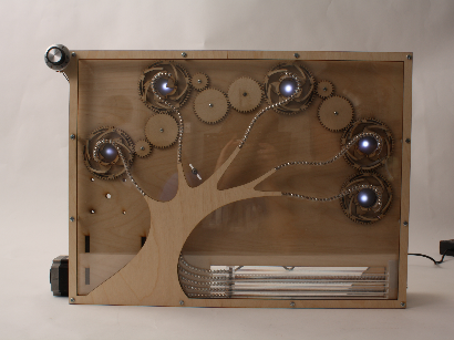
For our Elecanisms Final Project, we created the ElectriciTree, a kinetic sculpture of a living tree on a $250 budget in 5 weeks. The ElectriciTree features Buckyballs driven along tracks that function as tree branches, expanding and contracting. Five irises also open and close with the branches to reveal light.
Introduction
Goals
- The final product should be mechanically beautiful
- It should be self-contained and robust, so that it could be a permanent installation
- The electrical system should included a printed circuit board
Results
At the end of the project period, the software system, LEDs, and branch movement worked, but due to excessive friction, the irises could not move and were left open for demo purposes. The limit switches were also not attached, although they were confirmed working with the software system. Overall, we are satisfied with the way the project went, although there is a lot of interest in trying to make a v2 in the spring semester.
The Future
The goal of this project was to have an elegant piece of mechatronic artwork that could be displayed for Olin’s many visitors. We believe that this project resulted in a large step in the right direction, but some areas could use more work. Most of the work resides in using a material other than would for the iris gear chain, perhaps brass. In addition, we need to better mount the lead screw and add limit switches. From the software end, we'd like to add internet connectivity to the sculpture so that the tree could represent a live statistic, like energy usage in a home.
Next semester, we plan on applying for a student academic grant at Olin to fund our future endeavors with the ElectriciTree.
The Mechanical System
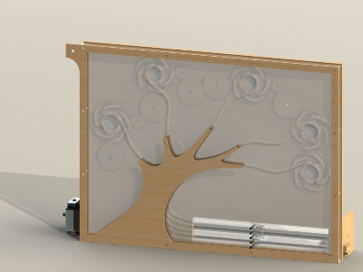
The mechanical system contains two main subsystems: an extending and contracting branch system and an opening and closing mechanical aperture system. The goal of the mechanical system was to have these two systems work in conjunction to provide a visualization of growth and decay of a tree.
The Branches
Inspiration
When determining the mechanism we would use to make the branches “grow,” simplicity and aesthetics were the two most important considerations. Simplicity is fairly self evident - given the limited time and money available, an easily implemented method was needed. Aesthetically, we wanted the growing mechanism to be elegant, continuous, and for the branches to be revealed, not predefined. Based on these criteria, we evaluated a number of different solutions.
Telescoping Branches
Our first thought was to create telescoping branches. However, telescoping mechanisms are both complex to manufacture well and only move in one direction, so capturing the flowing nature of tree branches would be very difficult.
Cables
In looking at ways to make the mechanism very simple, we turned to a marionette type system in which links were connected to one another and actuated. We planned to use a cable drive, but saw others attempt similar systems using linkages . Ultimately, this system was discarded for aesthetic reasons - we did not like being able to see the branches before they started to grow.
Roller Chain
Returning to having material “grow” from the tree trunk, we turned to pushing and pulling material along a guide rail. Our first attempt at this was roller chain, inspired by this video. This was the closest to the overall look we wished to achieve, but there was too much friction, especially moving the roller chain around bends.
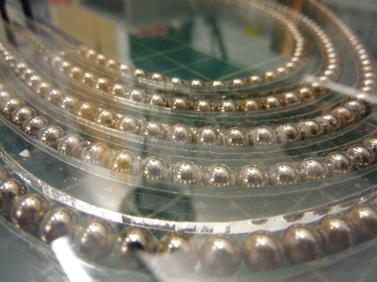
Ball Bearing/Spherical Magnets
Based on how visually appealing the roller chain was, we wanted to find a solution that would look similar but have a smaller bend radius. Ball bearings matched worked well for this, but maintaining continuity isn’t possible with ball bearings. Spherical magnets solved this last issue.
Track Design
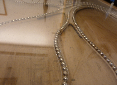
The tracks consist of three, ⅛” acrylic sheets and 5mm magnetic spheres. The path for each of the five branches is cut into the middle plate to guide the magnets and the outer two plates are used primarily to constrain the magnets and prevent them from falling out of the track. Acrylic was chosen because of its optical transparency. Other materials would have served between from a strength or friction standpoint, but using a transparent material means it is difficult to see the track, thus maintaining the revealing aspect as the branches grow.
One of the most difficult issues to deal with friction. As we experienced with the roller chain, pushing metal through curved paths in plastic makes the system difficult to drive. This issue was partially resolved by making gentle curves in the path rather than steep turns. Still, there was considerable friction. To reduce the friction to a manageable level, we coated the magnetic balls with a dry, Teflon lubricant.
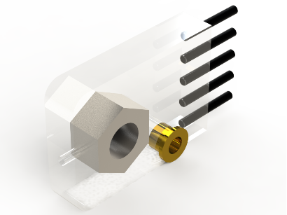
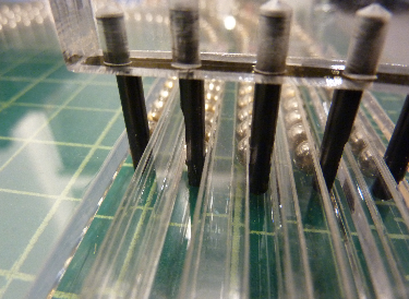
The Rake
Driving the magnetic branches forwards and backwards was achieved using a small “rake,” a part that has tines for each of the five paths. Each of these tines is an alloy steel dowel pin. Using steel means that the magnetic sphere that make up each branch are attracted to the tines, allowing them to push and pull the branches. The dowel pins are press fit into a small holder made from ½”, lasercut acrylic. This acrylic piece also holds a nut and bushing that connect it to the lead screw transmission.
The tines of the rake pass through small slots in the back most layer of acrylic to connect to the individual branches.
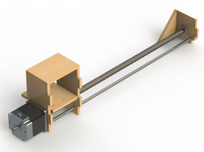
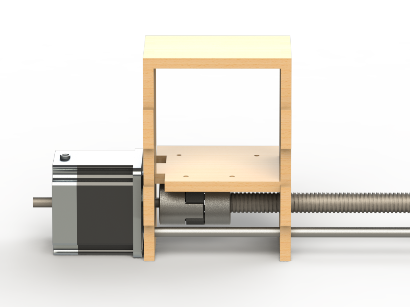
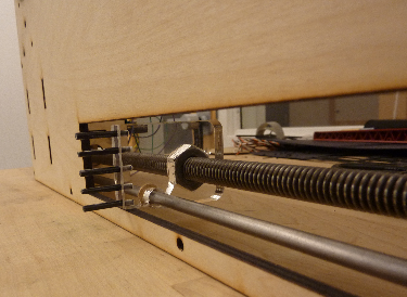
Lead Screw
Driving the rake to push the branches requires fairly accurate, high force linear motion. Lead screws fit all of these requirements and are cheap and easy to implement. The particular drive system we use consists of a ½” - 10 lead screw threaded through the nut in the rake and connected to a stepper motor using a spider shaft coupling. The spider coupler, although not allowing for as much torque to be transmitted, does allow for some slight manufacturing defects leading the misalignments and provides some damping for any mechanical chatter coming from the stepper motor. The lead screw support structure is lasercut from ¼” baltic birch plywood and can be easily connected and disconnected from the rest of the structure by slotting it in or out of mortise and tenon joints.
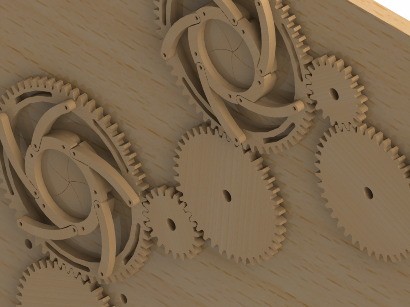
The Irises
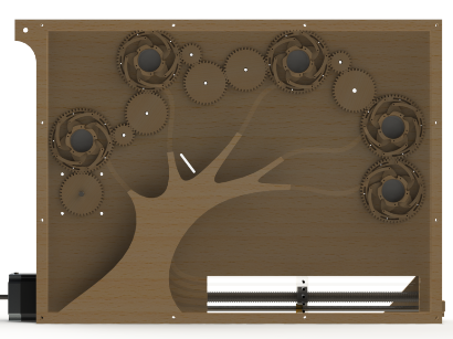
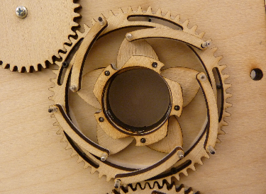 The aperture subsystem is made up of five mechanical irises connected in a gear train. The inspiration for the irises came from a previous Olin project worked on by one of the team members as well as other projects. Each iris has a range of motion of around 30 degrees and is actuated by rotating the outer race. The irises were positioned directly behind the curved ends of the branches so that the opening of the aperture is partially encircled by the path of the branch.
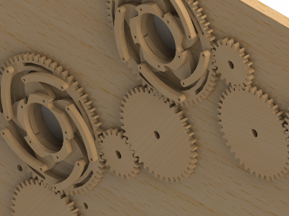
Since one of the goals of this project was mechanical elegance, the design decision was made to power the irises with a gear train. This fulfils this goal and allows the method of power transmission to remain transparent.The gear train that powers the irises is arranged approximately in a fibonacci spiral to add to the aesthetics of the gear train.
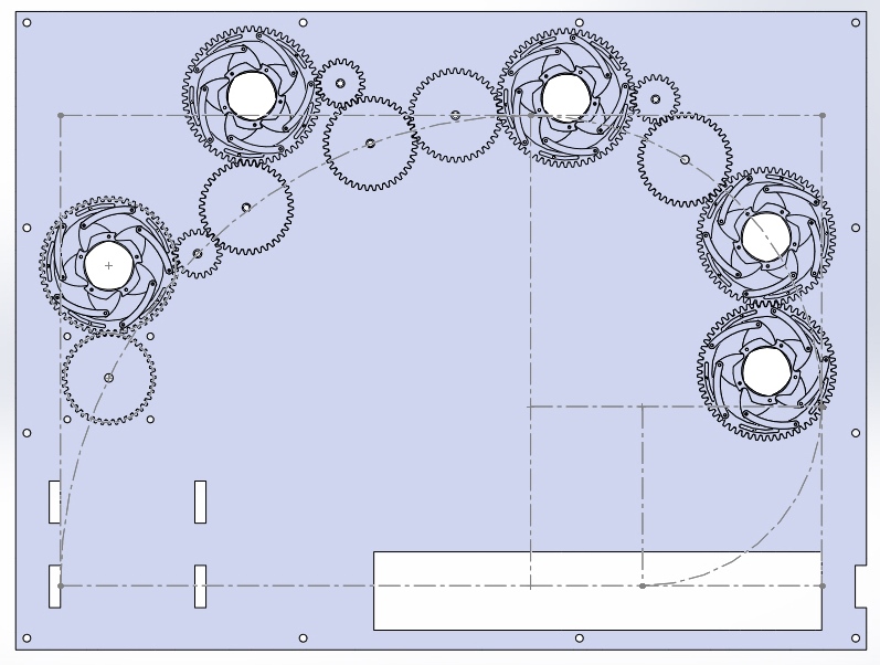
Overall the gear train has a 1:1 ratio so that each iris will open and close at the same rate as all the others. This was accomplished by a 2:1 ratio after each iris to account for the 2:3 ratio that occurs between the main gears and each iris.
The gears for this iteration were lasercut out of ⅛” Baltic Birch plywood. To reduce the friction in the system, sheets of Teflon were placed between the gears and the back plate. The irises themselves were also cut out of ⅛” Baltic Birch and were assembled using 1/16” dowel pins. The outer races of the irises move along slots that are restrained by dowel pins in the back plate. These slots were lubricated with graphite to further reduce friction. Overall the amount of friction in this system was relatively low until the pieces needed to be further constrained in order to have the system work while positioned vertically. This was done using epoxy and cyanoacrylate. This process did restrain the system but added more sticking points and increased the friction because the dowel pins were not epoxied perfectly orthogonal to the parts which increased surface area and reduced the amount of necessary play in the system. Another downside to the initial iteration is that the teeth of the wooden gears were slightly undersized because of the kerf of the laser used to cut them. This significantly increased the backlash of each gear which magnified the inefficiency of the system over the length of the gear train.
Because of this inefficiency the method of transmission changed as the system was assembled. The initial approach of transmission was to power a single gear with a stepper motor at the beginning of the gear train. However, powering from one side multiplies the inefficiencies across the remaining 12 gears (including the outer races of the 5 irises). This results in the irises at the end of the train not fully opening or closing with the rest of the system. To reduce these inefficiencies the decision was made to power the center gear so that by each end of the line the irises would only have the accumulated backlash of 6 gears. To accomplish this a timing belt and pulley system with tensioner was added to our assembly after most fabrication had occurred.
The Electrical System
The electrical system contains two main components: the custom PCB and the Elecanisms electrical board. The Elecanisms board features a PIC24F microcontroller which was utilized for the software that drove the motors and received user inputs. A major goal on the electrical sub team was to design and utilize a custom PCB as no one on the team had previously done so during their time at Olin. The custom PCB was created to house the motor drivers and an LED driver circuit.
Motor Driver
The mechanical system required two motors in total for the rake and irises. We found a few HT23-397 stepper motors that had been previously used in a Principles of Engineering project and used them as they would be easy to drive.
A requirement for the project was to use the course electrical board that had a PIC24F. The board was only able to supply 3 Volt logic, and the TB6560AHQ stepper motor driver chip that we planned on using required 5 Volt logic. We resolved this by adding a LM117T-5 5 Volt regulator and SN54HCT244-SP octal buffer to convert the 3V output to a 5V input.
Custom PCB
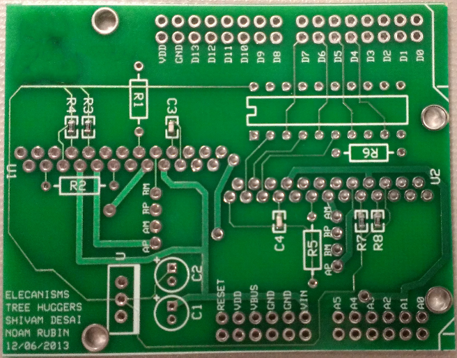
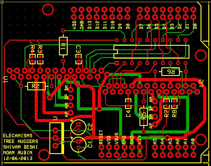 Our custom PCB wired together the PIC24F 12V and 3V power supply to our stepper motor drivers, 5V voltage regular, and LED drive circuitry. We had originally laid out the board using Eagle, with the intent to order through OSH Park, but due to time constraints, we used ExpressPCB.
The advantage of using stepper motors is having a lot of torque available, which helped overcome friction in the mechanical system. However, plenty of torque requires plenty of current, and this was the primary factor in laying out our PCB. All current paths between the motors and the 12V supply on the PIC are 0.40” wide, to ensure current can pass through the traces while dissipating sufficient heat. The choice of using 0.40” wide traces was made because we were expecting up to 1.5 Amps of current, and advice from peers suggested that while many trace width tables are conservative, allowing more heat to dissipate couldn’t hurt.
Unfortunately, we did not thoroughly check our traces for the octal buffer. Upon testing the PCB, we realized that we had flipped the positioning of the octal buffer, such that the outputs were feeding 5 volts into the 3V-tolerant pins on the PIC. Luckily, the 5V did not cause any obvious damage to the pins. We built a breakout out of proto-board to house the octal buffer, along with several wires we used to re-map the pins into the intended configuration.
LED Driver
We ordered high brightness LEDs to be used behind the irises. As the high brightness LEDs have a forward voltage drop of 3.2V and forward current of 18mA, we opted to use the 5V regulator as the power rail. We soldered five 100 ohm resistors directly to the leads of the LEDs and daisy chained the power and ground wires to the voltage regulator.
User Input
We used a potentiometer to control the position of the rake and provide an element of interactivity. The potentiometer was routed directly to an analog input on the board. In a surprising coincidence, there was a 1:1 mapping between the range of the potentiometer and the position of the stepper motor driving the rake.
Future Plans
We plan on removing the second stepper driver from the circuit as the irises can be driven using a servo motor. We also plan on integrating limit switches on the ends of the track to ensure that the motor never drives the system beyond its limits.
The Software System
While the control functionality for the ElectriciTree is simple, the software designed to run the tree is intended to be robust, and deal with both intentional and accidental design constraints. The software handles everything from reading a voltage from the potentiometer to moving the stepper motors and handling emergency signals from the limit switches (which are not currently installed). Much of the work in designing software involved creating a simple first order control scheme and properly filtering the input voltage from the pot. All of our code is open source, available at this repository.
Architecture
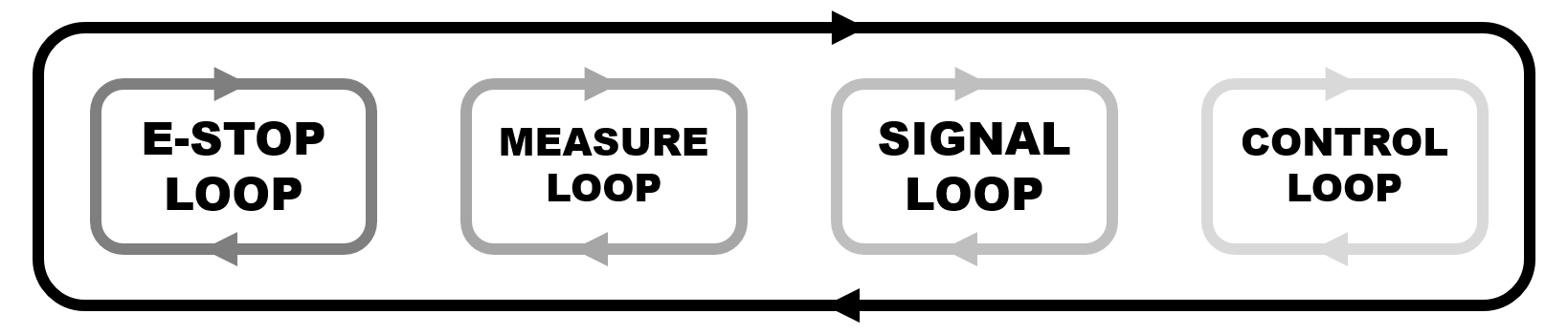
The software is architected around four loops, where each loop gets executed at different frequencies, thereby setting loop priority. Each loop is timed by a separate timer, and the asynchronous nature of the loop execution created some interesting programming challenges that were mostly solved by the use of global variables.
E-Stop Loop
The E-Stop Loop checks the limit switches to see if one has been triggered, debounces the switches due to noise on the digital input pin, and stops the motors if the switch is triggered. Due to oversight during the PCB design process, all pins on the PIC that supported input change interrupts were wired to the stepper drivers, so in order to properly stop operation of the motors during the press of a limit switch, the E-stop loop was executed every 1 μs.
Measure Loop
The measure loop received voltage measurements from the analog input pin to which the potentiometer was attached. This input was quite noisy, and could vary wildly on small time scales. In order to manage the noise from the potentiometer, two methods were used: an infinite impulse response (IIR) filter along with a peak rejection algorithm.
The IIR filter used was simple (it took only one parameter, α) and worked very well. Each time the measure loop executed, the new voltage value of the potentiometer was calculated using a weighted sum with the previous voltage:
new_pot_val = ( 1-alpha ) * pot_val + (alpha) * prev_pot_valThis weighted average prevented
new_pot_val from changing drastically between measurements. Through experimentation, we found that a value for α that worked well was 0.25. While this approach helped smooth the signal, it could not smooth out huge swings in the voltage read.
In order to handle large swings in voltage, we implented a simple peak rejection algorithm. When the potentiometer value is measured, if the new value is much, much larger than the previous value, the new value is set to the old one, thereby rejecting the new value. While this approach helped stabilize the stepper motor set points, it also rejected very fast and large manipulations of the potentiometer by hand, but we felt that this was a tradeoff worth making.
Signal Loop
The signal loop was exceedingly simple: it wrote the current value of a clk variable to the digital outputs for both steppers, and then inverted clk. This effectively created a square wave at a specific frequency, and since this code worked the first time we wrote it, we decided against using oc_pwm for this purpose. If it ain’t broke, don’ fix it!
Control Loop
The control loop handled the open-loop position tracking of the stepper motors, as well as controlling when the stepper motors stopped. Since the set point from the potentiometer could vary during the long period of the control loop, a function called within_interval was written to detect when the stepper motor position was within an acceptable interval from the desired set point. This made the stepper motors much more stable.
The Team
Shivam Desai
shivam {AT} students {DOT} olin {DOT} edu
Straight out of Lomita, California, majoring in Electrical and Computer Engineering with a focus in Robotics. Interests include robotics, bioinspiration, shape memory alloys, control theory, and violent-gory-bloodbath-"Oh my god Danny Trejo just used that guy's intestines to rappel down the building!" movies. Shivam was part of a team of six students who created a wall climbing robot in six weeks on a $250 budget. "Why do something ordinary when you can do something EXTRA- ordinary?"
Asa Eckert-Erdheim
asa {AT} students {DOT} olin {DOT} edu
Asa is from Durham, North Carolina and is majoring in Engineering with a concentration in Robotics. His interests span a wide variety of academic fields, including robotics (especially the bio-inspired sort), sustainability, space exploration and engineering education. Outside of Olin, Asa enjoys a new sci-fi book, a tasty cheese and music that is at least 20 years old.
Katherine Stegner
katherine {DOT} stegner {AT} students {DOT} olin {DOT} edu
Hailing from Moscow, Idaho, Katherine is neither Russion nor a potato farmer and is majoring in Mechanical Engineering. Her interests include building things that move as well as playing on playgrounds and eating toast.